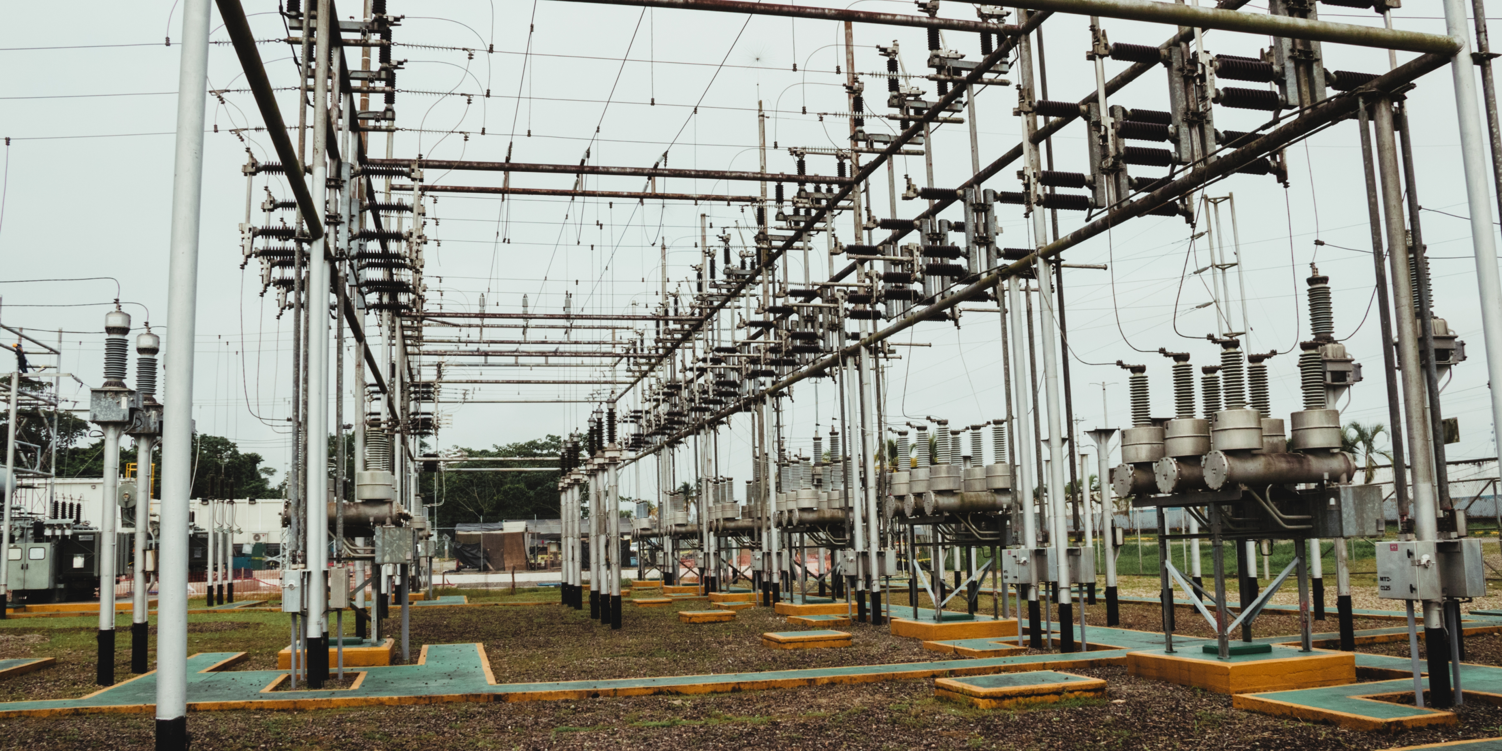
Electrical testing plays a crucial role in ensuring the accuracy, safety, and reliability of electrical systems and Components. FARE Labs performs the testing for the following Electrical devices/components;
Energy meter are electrical devices used to measure the amount of electrical energy consumed by a residence, business, or electrically powered equipment. They are typically installed by utility companies for billing purposes and come in various types, including electromechanical (analog) and electronic (digital or smart) meters. Energy meters record energy consumption in kilowatt-hours (kWh) and may also measure additional parameters like voltage, current, power factor, and frequency.
Energy meter testing involves verifying the accuracy of energy measurement and proper functioning of the meter under different load conditions, which is vital for fair billing and system monitoring.
| Product(s) / Material of test |
Specific tests/ parameters performed |
| Electrical and Electronic (Static) Energy meters/ Smart Meter |
AC Voltage Test |
| Insulation Resistance Test |
| Limits of Error |
| Meter constant |
| No Load condition |
| Starting Condition |
| Repeatability of Error |
| Voltage Variation ±10 percent |
| Frequency Variation ± 5 percent |
| Wave form:10 percent of third harmonic in the current |
| Reversed phase sequence |
| Power Consumption (Voltage Circuit) |
| Voltage Unbalance Test |
Current Transformers (CT) and Potential Transformers (PT) are essential components for measuring electrical parameters in high-voltage systems. These devices play a critical role in monitoring and protecting electrical systems, ensuring safe and efficient operation.
Current transformer (CT) testing ensures correct ratio, polarity, insulation, and burden characteristics to safely step down high currents for metering and protection. Similarly, potential transformer (PT) testing verifies the accuracy and insulation of the transformer used to step down high voltages, maintaining safety and precise voltage measurement.
| Product(s) / Material of test |
Specific tests/ parameters performed |
| Current Transformer (Metering Class Core 0.2S, 0.5S, 0.2, 0.5 & 1) (1A to 3200A) and
Voltage Transformer (Metering Class Core 0.2, 0.5, & 1) (1.1kV to 132 kV) |
Determination of Ratio Errors According to the Requirements of the Appropriate Designation or Accuracy Class |
| Determination of Phase Errors According to the Requirements of the Appropriate Designation or Accuracy Class |
| Terminal Marking and Polarity |
Earth pit is a designated excavation in the ground where an earthing electrode is installed to create a low-resistance path for electrical fault currents to safely dissipate into the earth. It is a critical component of an earthing (grounding) system, which protects both people and equipment by minimizing the risk of electric shock and preventing damage during fault conditions, such as lightning strikes or short circuits. Low earth resistance is desirable for grounding systems.
Earth pit testing is conducted to assess the effectiveness of an earthing system by measuring earth resistance, which is essential for fault current dissipation and personnel safety.
Soil resistivity is a measure of how much the soil resists the flow of electric current. It is a key parameter in designing effective earthing (grounding) systems, as it determines how easily fault currents can be dissipated into the ground. Soil resistivity is expressed in ohm-meters (Ω·m) and varies based on factors such as soil type, moisture content, temperature, and the presence of salts or minerals. Low soil resistivity is desirable for grounding systems because it ensures better conductivity and lower earth resistance.Areas with high soil resistivity may require special techniques—like using chemical electrodes, increasing electrode depth, or adding conductive materials—to achieve effective earthing. Soil resistivity testing is typically conducted using methods like the Wenner or Schlumberger method to help engineers design grounding systems that ensure safety and compliance with electrical standards.
Soil resistivity testing, often done prior to installing an earthing system, determines the resistance of soil to electric current flow and helps design an efficient earthing system by identifying suitable locations and materials. Together, these tests form a comprehensive approach to electrical safety, measurement accuracy, and system reliability.

